2 Existing Non-Standard Conditions shown in SHADED BOLD TYPE. Runways may be a man-made surface often asphalt concrete or a mixture of both or a natural surface grass dirt gravel ice or.
2
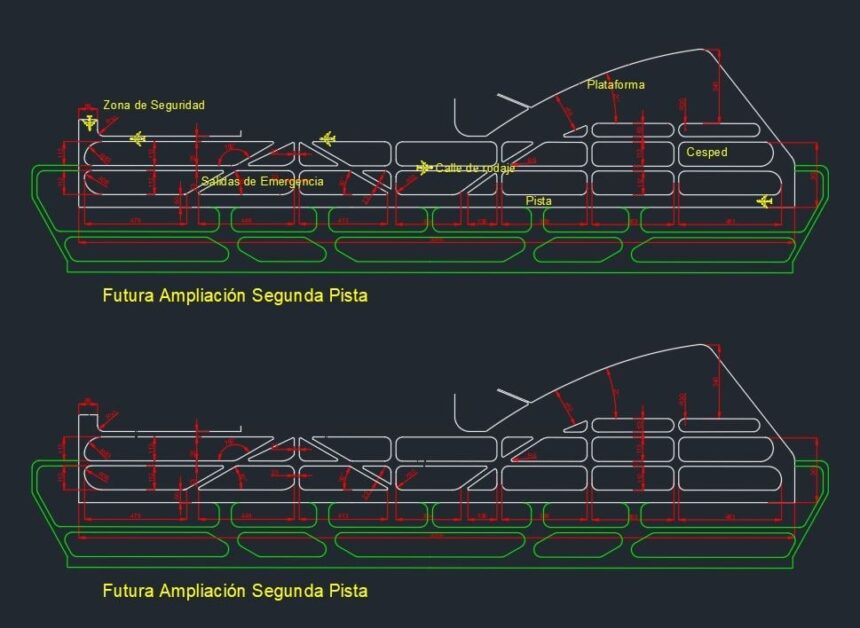
Taxiway f runway 5-23 taxiway c runway 11-29 taxiway anorth taxiway dnorth taxiway asouth runway 11-29.
. Taxiway A taxiway is a path for aircraft at an airport connecting runways with aprons hangars terminals and other facilities. DGR Engineering collaborated with a long-standing airport engineering partner at the Watertown SD Regional Airport to provide electrical design and construction services for the airport including runway and taxiway lights lighted signs and airport electrical systems upgrades. CE8702 RADHE Unit 1 notes Download Here.
AC 1505300-13A Taxiway Fillet Design Tool. Direction Sign for Runway Exit While on the runway this sign will indicate the approaching taxiway. Code number and is not intended to influence the actual runway length provided.
DOCKS AND HARBOUR ENGINEERING Notes free download. AIRPORT DESIGN STANDARDS AND RUNWAY LENGTH CHAPTER 3 PullmanMoscow Regional Airport Master Plan Phase 1 3-3 NOTES. International Airport Layout Plan and Elevation CAD Template DWG.
44 Chap 4 OUTER COMMON CURVE C RUNWAY C TAXIWAY L L Figure 4-5. Layout of taxiways 1 Arrangement 4 Higher turn-off speeds 2 Busy airports5 Route 3 Crossing 6-3. The standards for the taxiway design and construction will therefore not be as rigorous as for the runway.
Bypass taxiway Entrance Taxiway. Closed Runway and Taxiway Marking Located at both ends of permanently closed runways and at 1000ft intervals. Taxiway design Turning Radius where R is the radius of curve in m V is ther speed in kmph and f is the coefficint of friction between the tyre and pavement surface the value of f may be assumed as 013.
The phase 3 construction is delineated to. Airport Design ReferenceAC1505300013A. The FAA Office of.
If you have suggestions for improving this Users Guide or the Taxiway Fillet Design Tool you may use the. This assists the design of runway taxiway terminal buildings and the drainage system. Geometric Design Standards Length of taxiway Width of taxiway Width of safety area Longitudinal gradient Transverse gradient Rate of change of longitudinal gradient Sight distance Turning radius.
FAA Advisory Circular 1505300-13 Change 9 Airport Design September 2005. This Users Guide provides the steps for operating the Taxiway Fillet Design Tool. It is located at the far end of the intersection.
Purpose of this Guide. The term OMGWS is an important input parameter when determining runway and taxiway widths. 3 Existing airfield design standards applicable to Pullman-Moscow Regional Airport.
Airport Control Tower Elevator Details CAD Template DWG. Runways Runway Shoulders and Blast Pads Runway Safety Areas Runway Object Free Areas RUNWAY DESIGN. For airport serving large subsonic jet transports minimum value of redius of curvature is 120 m whatever be the speed.
Feedback Form at the end of this document. Compliance with current directives EASA CS-ADR-DSN ICAO Aerodrome Design and Operations Annex 14 Volume 1 Appendix 1-3 ICAO Aerodrome Design and Operations Annex 14 Volume 1 Appendix 4 ICAO Aerodrome Design Manual Part 6 Frangibility FAA AC 150. TAXIWAYRUNWAY AND RUNWAYRUNWAY HOLDING ILS CRITICAL AREA HOLDING This sign is located at the holding position on At some airports when the instrument landing system taxiways that intersect a runway or on runways that is being used it is necessary to hold an aircraft on a intersect other runways.
This project involved the installation of improvements at an active. Removals within taxiway c object free area phase 4 asphalt milling and other removals within taxiway g. The length of a taxiway depends upon the distance.
RUNWAY DESIGN Standards RUNWAY DESIGN Runway Design Standards Guidance provided in Chapter 3 of FAA AC 1505300-13A Also in ICAO Annex 14 Aerodrome Design and Operation Used to determine physical dimensions for. Geometric design of runway intersection Questions 5 Chapter 6 TAXIWAY DESIGN 6-1. This marking is also placed at taxiway entrances that are closed.
Minimize the closure time of taxiway c and taxiway g. Geologically Sriperumbudur belongs to the Sriperumbudur Formation which is characterized by erinaceous and argillaceous rock units comprising of splintery green shale clays and sandstones with ironstone intercalation and conformably overlying either the. 1 Single runway 2 Parallel runways 3 Intersecting runways 4 Divergent or open V-runways 5-9.
Asok DACHARLA mtech 1 st year Gmr institute of technology Taxiway Taxiways are defines as paths on the airfield surface for the taxing of aircraft and are intended to provide linkage between one part of the airfield and another. Note 2 Guidance on determining the runway length is given in the Aerodrome Design Manual Doc 9157 Part 1 Runways. AVM 3202 AIRPORT DESIGN.
For aircraft with a CMG and MGW combination in the TDG 2 category use the ADG and TDG Classification Tool below to calculate TDG 2A and 2B. EB-75 AC 1503500-13A Ch1. Orientation Wind Rose Diagram Runway length Problems on basic and Actual Length Geometric design of runways Configuration and Pavement Design Principles Elements of Taxiway Design Airport Zones Passenger Facilities and Services Runway and Taxiway Markings and lighting.
Limit the number of runway crossings. DESIGN ELEMENTS OF TAXIWAY. Entrance taxiway OUTER COMMON CURVE BYPASS TAXIWAY ENTRANCE TAXIWAY NO TAXIWAY ISLAND C RUNWAY C TAXIWAY L L Figure 4-6.
Airport Staircase Elevation and Reinforcement Details CAD Template DWG. Comparison of runway patterns 5-10. Anna University CIVIL RADHE.
REDIM is a computer model developed to locate and design high-speed runway and right angle exits at airports. TOP 10 Websites to Download CAD DWG Files. Runway Sign Taxiway Guidance Sign Stand Information Sign 3.
Airport Antenna Site View Layout CAD Template DWG. Introduction To Runways According to the International Civil Aviation Organization ICAO a runway is a defined rectangular area on a land aerodrome prepared for the landing and takeoff of aircraft. Optimize taxiway flows to limit the amount of runway crossings.
After numerous studies concluded that nonstandard taxiwayrunway geometry was a contributing factor in many runway incursions and wrong runway takeoffslandings the 2012 release of Federal Aviation Administration FAA Advisory Circular 1505300-13A Airport Design included new standards and recommendations for airport design. 21414 2 AC 1505300-13 CHG 17 9302011. The model uses kinematic equations to characterize the aircraft landing.
Airport Design Tools. UNIT IV AIRPORT DESIGN CE6604 notes. Geometric Standard for Taxiway Following eight elements of the geometric standards for Length of taxiway.
Orientation Wind Rose Diagram Problems on basic and Actual Length Geometric Design Elements of Taxiway Design Airport Zones Passenger Facilities and Services Runway and Taxiway Markings. Taxiway runway intersections should be 90 degrees whenever possible this allows a pilot to have good visibility in both directions before crossing except high-speed exits. Aircraft movement on taxiways are essentially ground movements and are relatively slow compared.
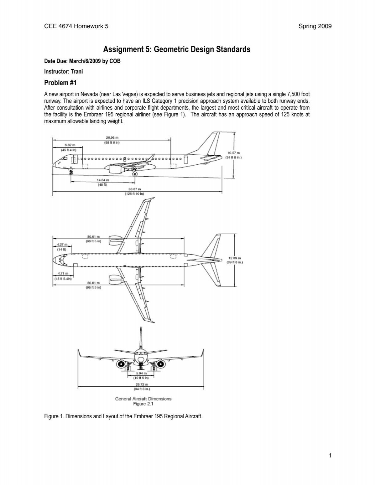
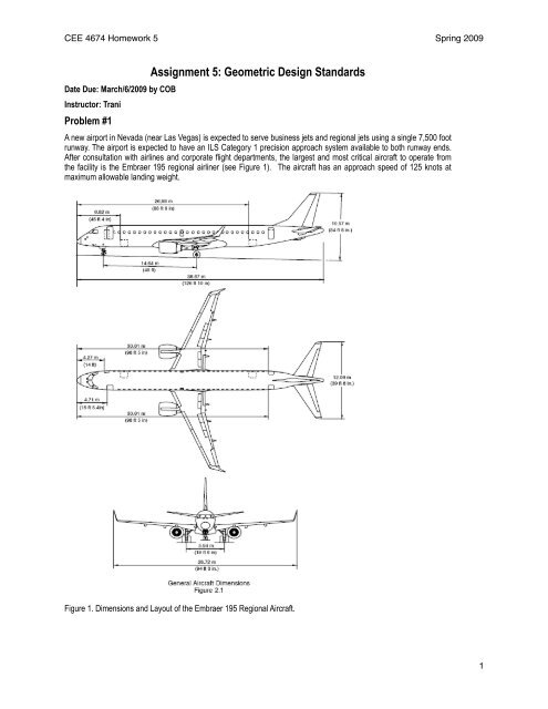
Assignment 5 Geometric Design Standards

Design Of Concrete Airport Pavement By Mebuild Issuu

10 Runway Design Highway And Airport Engineering Dr Sherif El Bada
Aerodrome Design Manual Part 4 Visual Aids Doc 9157 Part 4 Icao Store
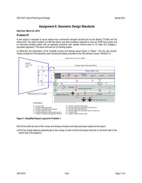
Assignment 6 Geometric Design Standards

Aircraft Airplane Illustration Airplane Art Aircraft Design
Airport Runway Design Autocad Drawing
Assignment 5 Geometric Design Standards
0 comments
Post a Comment