From Table 1 Load by earth fill. Flexible Pipe - a structure that transmits the load on the pipe to the soil at the sides of the pipe.

Reinforced Concrete Box Culvert Using Sap2000 This Sap2000 Tutorial Provides Modelling Analysis Design Of Reinforced C Reinforced Concrete Sap2000 Concrete
The available values are.

. H L the head loss in the culvert barrel for full pipe flow ft US. General Culvert Design Method 1. Culvert Manual CM 34 - LRFD Culvert Design Loads May 2019 Page 5 According to Article 121121 live load distribution is dependent on fill height.
An equation that relates culvert parameters for outlet control conditions in a pipe culvert design spreadsheet is. Hydrologic analysis methods are described and references cited. The parameters in the equation are as follows.
Inlet type As the drainage channel is poorly defined and the upper canal bank is only 4 ft higher than channel invert a type 3 or 4 inlet transition will be good. 13 with hydrologic storage routing and special culvert design information. A is the cross-sectional area of the culvert in ft2 m2 for SI.
HDS-5 culvert design methods are based on design charts and nomographs. Sometimes a small increase in flow rate can affect a culvert design. Click on Load button to load an existing culvert file to view or modify it or a new file to start a fresh design.
The result is a comprehensive culvert design publication. Rcc Box Culvert Design Example. Circular pipe culverts are widely used in transportation applications to transport stormwater under roadways railways etc.
Y and c are constants dependent on the type of culvert and type of inlet. Adopt RCC NP3 heavy duty non pressure pipe for carrying heavy road to traffic. DRAINAGE CRITERIA MANUAL BRIDGE AND CULVERT HYDRAULIC DESIGN City of Bella Vista AR CB-1 10 CULVERTS INTRODUCTION AND OVERVIEW The purpose of this chapter is to provide guidance for culvert and bridge hydraulic design.
This brochure explains the average density of concrete pipe as compared to corrugated PE pipe. 272 DESIGN CONSIDERATIONS 2721 Headwater Any culvert that constricts the natural stream flow will cause a rise in the upstream water surface. A cast in- situ headwall extension with minimum thickness as specif ied in the standard drawing 1243 Drawing 2 and 3 shall be used to connect the precast headwall and the pipe or box culvert.
958 Culvert Design Form 9-43 96 DESIGN EQUATIONS 9-34 961 General 9-34 962 Approach 9-34 963 Inlet Control 9-34. 42 Structural Design of Culverts 421 Introduction Structural design of a culvert must be performed to ensure that the culvert is strong enough to resist the loads that will be imposed upon it. Calculate the culvert design flows Section 3-31 2.
Hydraulic Design series No. Q is the design discharge through the culvert in cfs m3s for SI. From the Solve For list select the value that you want to calculate.
If only the design peak discharge is used in the design the engineer cannot assess what effect increases in the essential design discharge will have on the culvert design. For example a circular shape. 3 7 6 w 6 6 B ft L ft inches t inches H ft Page 28 Design Example Pipe Friction.
Determine the type of control that exists at the design flows either inlet control or outlet control Section 3-34 5. Determine the tailwater elevation at the design flow Section 3-33 4. It is the structural element that allows the movement of the vehicles.
5000 package of 25. Example culvert design 2004 lecture 22 example culvert design much of the following is based on the usbr technical publication of small canal 1978 an example. Considering height of culvert.
Pipe Culvert Outlet Control Design Calculations. D is the inside height of the pipe culvert in fr m for SI. Discharge Headwater and Size.
LOAD BY EARTH FILL Total height. Corrugated metal and concrete are used for many of these pipe culverts. SEPTEMBER 2013 LRFD BRIDGE DESIGN 12-4 minimum top slab thickness is 9 inches and the minimum bottom slab is.
458-1971 For pipe of Internal Diameter 100 m Outer Diameter 120 m. Or m SI. These charts and nomographs are based on data from hydraulic tests and on theoretical calculations.
As per the nature of the structure the following components included in a box culvert. Pipes and box culverts. 113400-13234543113400-128 31 m.
Buried structures with horizontal dimensions less than 10-0 are not classified as bridges. From the Structure menu in the Hydrology Module choose Pipe Culvert Design to display the design dialog. Culvert pipe under roadway approaches ie driveway shall have.
Determine the allowable headwater elevation Section 3-32 3. The horizontal distance from the culvert inlet to the pipe outlet is from left to right. Pipe Culverts Page 27 Design Example Inlet Type 3.
There is scatter in the test data and the selection of a best fit design equation. The actual headwall extension dimensions shall be determined to suit the project specific culvert. Culverts diameter or height greater than 1200.
2018 - f design example double 12 x 12 for example metal pipe culverts were always considered do not place reinforced concrete box culverts on pilesFree Download Here pdfsdocuments2 com April 25th 2018 - 4 3 Illustrate different type of accounts with example Understand the design of RCC. Use type 3 transition Fig. Box Culverts 1223 Design Guidance for Box.
The minimum diameter of culvert pipes under a main roa dway shall be 18 inches. C h a p t e r 9 ²C u l v e r t s 9-5. HW is the headwater depth above the invert at the inlet in ft m for SI.
Proposed roadway stationing of the culvert location. Box Culvert - A culvert in the shape of an enclosed rectangle and consisting of a bottom slab two wall elements and a top slab. The American Concrete Pipe Associations precast concrete box section program was implemented to develop a product for these applications and.
The distribution of live loads for fills 2 feet shall be according to Article 46210 and for fills. 5 combines culvert design information previously contained in Hydraulic Engineering Circulars HEC No. Designer - Individuals designated by the Structural Engineer to use this manual to design and detail culverts.
Typically these smaller buried. Culvert hydrology and hydraulic calculations as described in Section 3-3 and Table 3-2. Examples of flexible pipes are plastic and thin walled metal pipes.
Box culvert is a rectangular shape reinforced concrete structure consists of single or multiple boxes allowing movement of water and traffic. The correlation between the design equations and the design nomographs is not exact. The emphasis in this Chapter is on the design of culverts for urban stormwater drainage.
Highway authorities may have different or additional requirements which are not discussed herein. The proof is in the pictures of this brochure that show jetting or collapse of high density polyethylene culverts and the roadways because of flotation. 2500 package of 25.
Culvert Extension - A portion of a culvert built beyond the limits of a previously existing culvert. Major design parameters for culvert design are the diameter and slope of the pipe for a specified culvert material. Cast-in-place reinforced concrete box culverts have been designed and used for many years because of special waterway requirements unusual load conditions or designer preference.
Height of embankment over pipe. The strength of a culvert depends on the strength of the materials that are used and the shape of the culvert barrel. The primary objective of a culvert or bridge is to convey stormwater flows based on a design flow rate through.
The site and any possible hazards.

Culvert Hydraulics Basic Principles

Design Draw A Pipe Culvert With 3 Vents Examples Part 1 Youtube
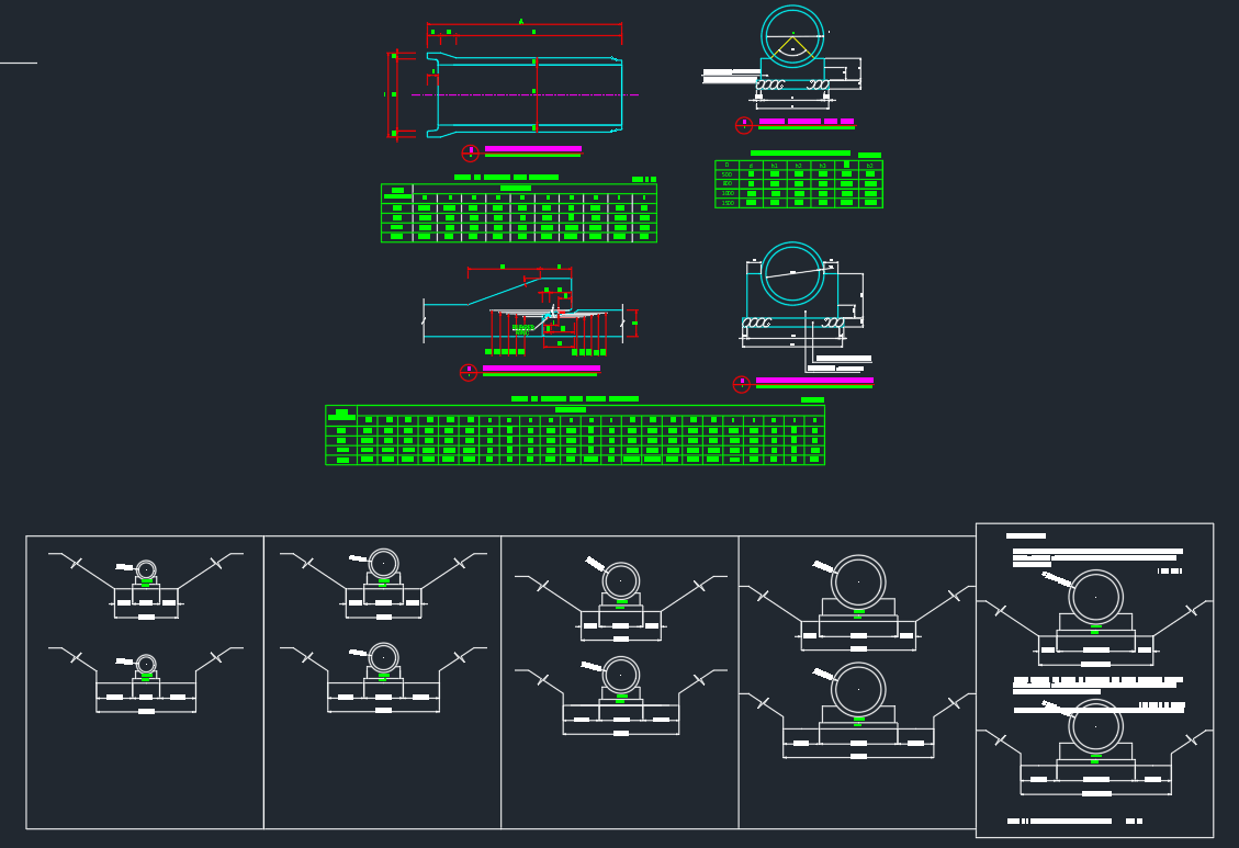
Pipe Culvert Details Autocad Drawing
Wingwall Of Culvert Free Drawing Culvert Bridge Design Autocad
2
2
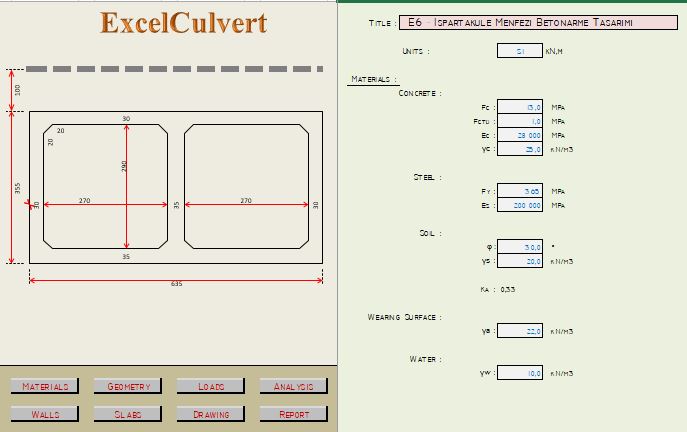
Concrete Box Culvert Analysis And Design Spreadsheet

What Is Culvert Types Materials Location And Advantages Daily Engineering Culvert Concrete Concrete Patio
0 comments
Post a Comment